Forum Replies Created
-
AuthorPosts
-
in reply to: New firmware branch on Github #4071
@Cracked wrote:
Just wanted to bring your attention to a new fork of the firmware repository in GitHub.
http://www.github.com/TheBeansTalk/OsPID-Firmware
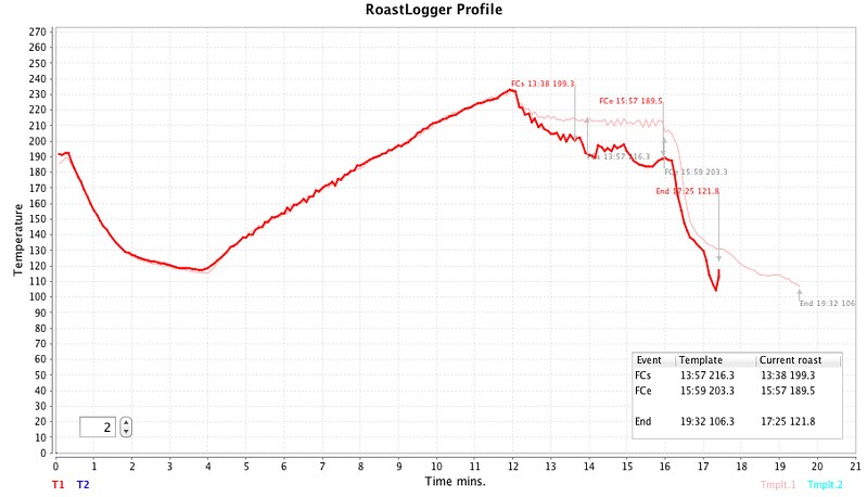
The main objective of this fork is to facilitate communication between the osPID and freely available coffee roasting software (RoastLogger). Currently only a bit of a hack to output to serial in a string format which can be understood by RoastLogger. A work in progress.
Hi,
I made some changes in the original roastlogger firmware to recognise ospid.
But your approach is better, as the dashboard remains unchanged.
Maybe my ino file could give some ligth to make the necessary changes to make ospid work fine with roastlogger.
If so, please let me know.
Thanks.#include “Adafruit_MAX31855.h” // here i added the thermocouple (my board is custom made)
int thermoDO = 12;
int thermoCS = 11;
int thermoCLK = 13;Adafruit_MAX31855 thermocouple(thermoCLK, thermoCS, thermoDO);
// here i made the changes needed to roastlogger understand the temperature measured by OSPID board
t1_cur = thermocouple.readCelsius();
t2_cur = (thermocouple.readCelsius();// heater = roundOutput( heater );
if (heater >= 0 && heater <101) {
output1.Out( heater, 0 ); // update the power output on the SSR drive Ot1// here the values added in roastlogger program are executed in the board
pinMode (3, OUTPUT);
analogWrite (3, (2.55 * heater));in reply to: Using a 16×2 LCD #4055shi$&#$!
the posting took all my blank spaces
example: lcd.print(F(“DashBrd********”))
take all the * and put blank spaces instead.
This will work. You have to remember the OSPID LCD show only 8 caracters, everything after that will not be showed, so the programer didn’t bother with the artifacts. Putting blank spaces after the words will put the artifacts after the 16 caracters, RESOLVING THE Artifact problem.in reply to: Using a 16×2 LCD #4054Use these lines in your sketch
lcd.print(highlight? ‘>’:’ ‘);
switch(index)
{
case 0:
lcd.print(F(“DashBrd “));
break;
case 1:
lcd.print(F(“Config “));
break;
case 2:
lcd.print(tuning ? F(“Cancel “) : F(“ATune “));
break;
case 3:
if(runningProfile)lcd.print(F(“Cancel “));
else lcd.print (profname);
lcd.print (” “);
break;
default:
return;
}break;
case TYPE_VAL:switch(index)
{
case 4:
val = setpoint;
dec=1;
icon=’S’;
break;
case 5:
val = input;
dec=1;
icon=’I’;
canEdit=false;
break;
case 6:
val = output;
dec=1;
icon=’O’;
canEdit = (modeIndex==0);
break;
case 8:
val = kp;
dec=2;
icon=’P’;
break;
case 9:
val = ki;
dec=2;
icon=’I’;
break ;
case 10:
val = kd;
dec=2;
icon=’D’;
break ;default:
return;
}
lcd.print(edit? ‘[‘ : (highlight ? (canEdit ? ‘>’:’|’) :
‘ ‘));if(isnan(val))
{ //display an error
lcd.print(icon);
lcd.print( now % 2000<1000 ? F(" Error"):F(" "));
return;
}for(int i=0;i
isNeg = num<0;
if(isNeg) num = 0 – num;
didneg = false;
decSpot = 6-dec;
if(decSpot==6)decSpot=7;
for(byte i=6; i>=1;i–)
{
if(i==decSpot)buffer = ‘.’;
else {
if(num==0)
{
if(i>=decSpot-1) buffer=’0′;
else if (isNeg && !didneg)
{
buffer=’-‘;
didneg=true;
}
else buffer=’ ‘;
}
else {
buffer = num%10+48;
num/=10;
}
}
}
lcd.print (” “);
lcd.print (buffer);
break;
case TYPE_OPT:lcd.print(edit ? ‘[‘: (highlight? ‘>’:’ ‘));
switch(index)
{
case 7:
lcd.print(modeIndex==0 ? F(” M Man “):F(” M Auto “));
break;
case 11://12:lcd.print(ctrlDirection==0 ? F(“A Direc”):F(“A Rever”));
break;
}in reply to: Using a 16×2 LCD #4053YES,
ADD SOME BLANK SPACES BEFORE THE VALUES PARAMETERS IN THE SKETCH
in reply to: Wierd Input error and hard to get no overshoot. #3963I think the problem resides at the thermocouple touching metalic parts. Any electral static could result in read errors. I used to had the same problem until I isolated the thermocouple from all metalic parts of my oven and of my homemaid coffee roaster. After did this, no read errors at all.
http://www.youtube.com/watch?v=0GXYzxPXTLQ&feature=player_embedded
Using roastlogger (my OSPID is a custom version, assembled by me)
http://farm6.staticflickr.com/5506/11169363445_29a7b40336_c.jpgin reply to: What type of K-type thermocouple is required? #4052Any of it will work with the OSPID. however, I don’t know if the grounded thermocouple will work.
in reply to: PORTING OSPID FRONTEND TO ANDROID #4049@Cracked wrote:
Could you provide any details of how you added bluetooth?
You have to connect this Bluetooth dongle to the pins 0 and 1 on the arduino.
http://dx.com/p/104299I Builded my own version of OSPID (using the software provided by Brett). So, I don’t know where to connect the pins from bluetooth dongle to the original OSPID. Maybe Brett can assist you.
in reply to: Dual output relay and SSR at same time #4039Already did that. I added a few lines in the firmware to do it. I use the OSPID frontend to roast coffee, so, keeping the temperature in line during the ramps, and having fast response when decreasing temperature is very important.
-
AuthorPosts