Project Description
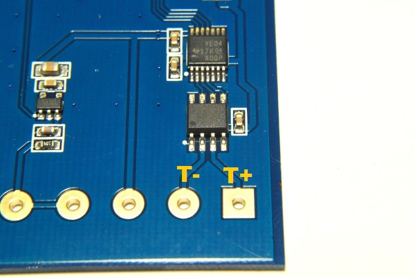
As hardware bugs go, we got lucky. This is pretty easy to fix. We just need to insert a 10 nF ceramic capacitor (preferably low ESR) across the T+ and T- pin of the MAX31855KASA IC.
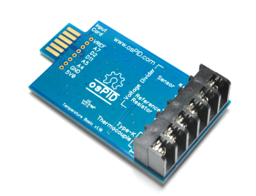
An unmodified v1.20 board will look like this:
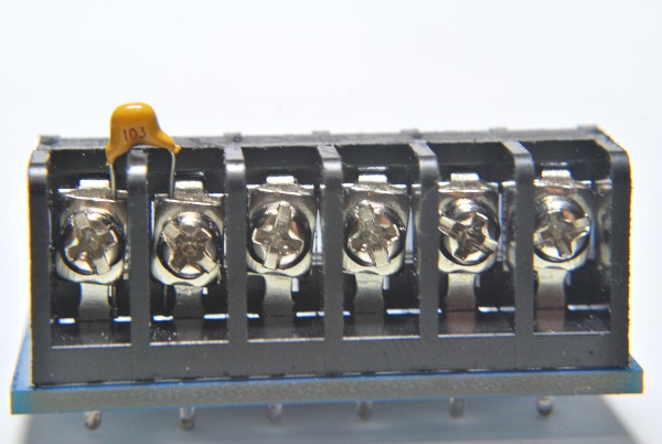
Method #1: Capacitor (TH) Inserted at the Terminal Block
If the thermocouple leads that you are using is of similar size with the lead of the through hole ceramic capacitor, this is the simplest method to do it. However, if your thermocouple leads size is thinner than the capacitor leads, it will be better to use one of the other methods as the thermocouple leads might be loosely connected to the terminal block.
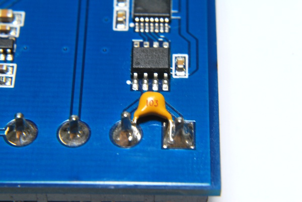
Method #2: Capacitor (TH) Soldered on the Terminal Block Pads
This method is better if you have access to a soldering iron and want the capacitor to be permanently fixed onto the board. You may need to trim the capacitor leads if they are too long.
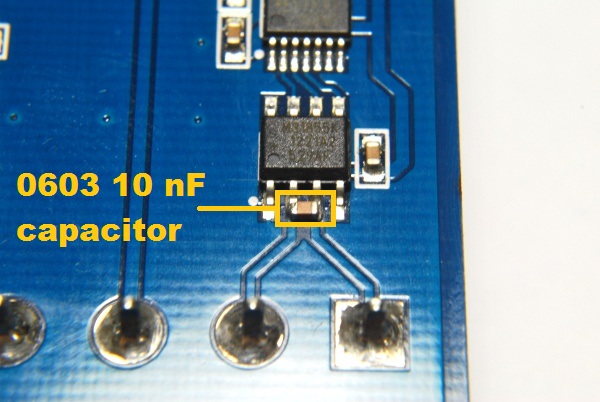
Method #3: Capacitor (SMT) Soldered on the MAX31855KASA+ Pads
This method uses a small SMT (0603 in the picture) 10 nF X7R capacitor soldered onto the pads of the MAX31855KASA+ IC. This is the method we are using. (boards shipped ”’after August 18, 2012”’.) If you are more comfortable with other bigger SMT sizes like 1206, you can mount one of those between the terminal block pads instead.