Project Description
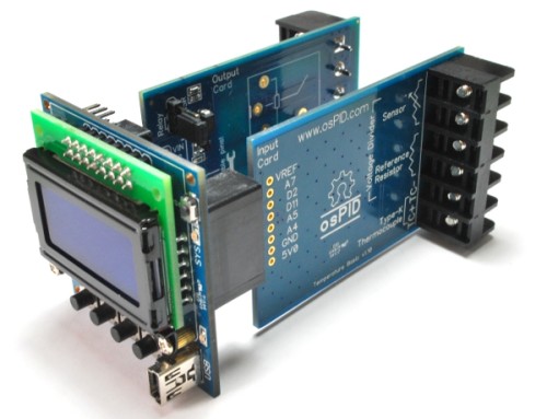
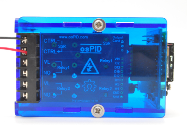
The digital output card has 3 output (maximum only 2 operating simultaneously) ports.
The output port is tied to pin D5 and D6 of osPID main board:
- Pin D5 is configured to drive a relay.
- Pin D6 is configured to either drive a relay or an external SSR.
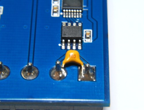
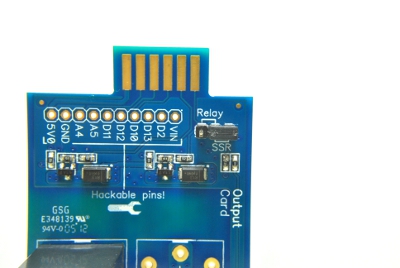
To drive the relay (not soldered by default) on pin D6, the selection jumper need to configured as below:
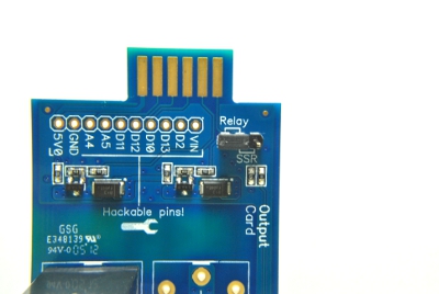
To drive an external SSR on pin D6, the selection jumper need to be configured as below:
To decide whether you need to use the on board relay or an external SSR depends on the following requirements:
- Do you need the osPID unit and the load voltage to be optically isolated?
- Is the load current exceed that of the on board relay?
- Do you have some allergy towards relay clicking sound?
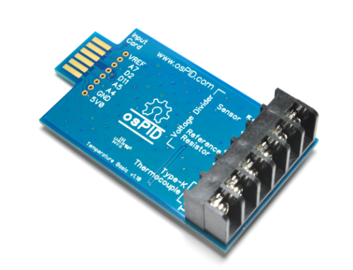
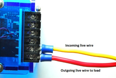
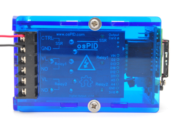
If you have chosen to use the on board relay driven by pin D5 (labelled as Relay 2 on the card), you’ll need to connect the live (hot) wire into the VL spot (5th terminal from the top) and another wire to your load (oven, heater). Please take note of the wire size required to carry the load current in your setup.
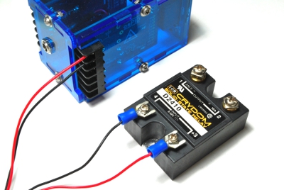
Using External Solid State Relay (SSR)
If you have chosen to use an external SSR driven by pin D6 (labelled as SSR on the card), depending on the hardware revision of your digital output card, the wiring should be as follows:
| v1.50 | v1.70 |
|---|---|
|
|
 |
 |
It is recommended to use a color coded wires in the setup.
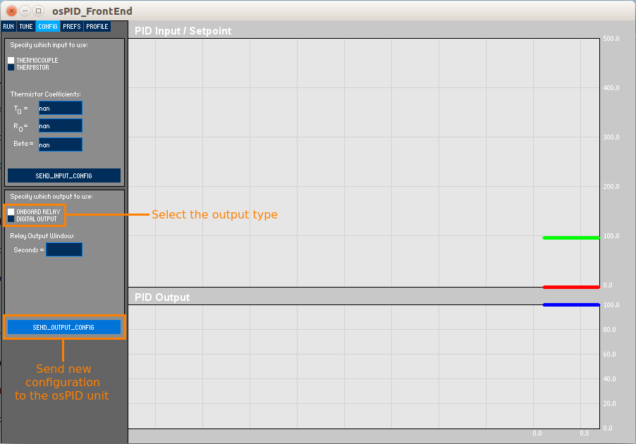
If you need to change the default configuration, you can do this through the osPID front end software. Under the “CONFIG” tab in the front end software (settings will only appear once the osPID unit is connected), you can configure the output to be either on-board relay or digital output (referring to driving an external SSR). Once you have selected the desired output, you’ll need to send configuration to the osPID unit: